Reading a CMM inspection report: what every column tells you about your stainless parts
October 18, 2026
A CMM report lands in your inbox with a column of green numbers and a pass stamp. Most buyers file it and move on. That is a missed chance, because the report holds the evidence of how the part was measured, and a badly set up measurement can pass a part that does not fit. Stainless parts add their own traps: work-hardened thin walls spring when clamped, slender parts bend under probe force, and a part measured warm can read larger than the same part at 20 °C.
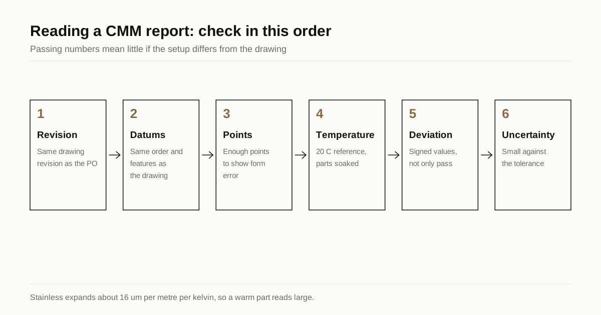
This guide shows what each section of a typical report means, what to check before accepting the numbers and which questions to put to the shop.
What the machine actually does
A coordinate measuring machine touches the part with a probe at many points and records the coordinates in three axes. Software then fits geometry to the points, for example a circle to the points on a bore, and reports the size and position of each feature. It can also compare features with each other, for example how far a hole centre sits from a datum plane.
The result depends on the setup as much as on the machine:
- how the part is held,
- which datums define the coordinate system,
- how many points are taken per feature,
- the probe size and how it is calibrated,
- the temperature of the part and the machine.
A report that does not state these items leaves you guessing.
The columns in a typical report
| Column | What it shows | What to check |
|---|---|---|
| Balloon or feature number | Links to the ballooned drawing | Every drawing dimension has a number |
| Description | Feature type, for example diameter or position | Matches the callout on the drawing |
| Nominal | Drawing value | Same as the drawing, including revision |
| Upper and lower tolerance | Allowed limits | Same as the drawing |
| Measured (actual) | What the machine found | Reasonable decimals, not rounded |
| Deviation | Measured minus nominal | Sign and size, not only pass or fail |
| Out of tolerance | Amount beyond the limit | Any value here must be explained |
| Status | Pass or fail | Check it follows from the numbers |
A sample line might read: balloon 7, diameter, nominal 12.000 mm, tolerance ±0.010, measured 12.004, deviation +0.004, pass. The deviation tells you more than the pass: this part sits on the high side of the band, and if the next five also read +0.004 to +0.008, the process is drifting.
Datums and alignment: the part most buyers skip
Geometric tolerances such as position, flatness and perpendicularity depend on the datum reference frame. The CMM must establish that frame the way the drawing does, using the datum features in the specified order. If the shop aligns the part differently, for example on the bottom face when the drawing says datum A is the top face, the position results are wrong even if the numbers look good.
Check that:
- The report lists the datums and their order.
- They match the datums on the drawing.
- The feature of size for datum B or C is stated as MMC, RFS or LMC if the drawing says so.
- The drawing follows ASME Y14.5 or ISO GPS, and the report says which.
If the drawing has no datums, the report cannot be checked either. The RFQ checklist says to send a drawing with datums and critical dimensions marked.
Number of points and form error
A circle can be defined by three points, but a real bore is never a perfect circle. Taking more points shows form error such as ovality and lobing. For a precision bore in stainless, 12 to 24 points per section is common, while three or four points would hide a triangular form.
Look for these items:
- the number of points per feature,
- the form error value, for example roundness or cylindricity,
- the fit algorithm: least squares, maximum inscribed or minimum circumscribed.
A shop that reports 12.004 from four points may see 12.010 from 24 points. For tolerances under ±0.01 mm this matters. The tolerance guide puts numbers on how tight bands add cost, and measuring them correctly is part of that cost.
Stainless-specific measurement traps
Stainless steel parts have a few behaviours that affect measurement.
| Trap | Cause | Effect | Control |
|---|---|---|---|
| Thermal growth | Austenitic stainless expands about 16 µm per metre per kelvin | A 100 mm part 3 °C warm reads about 5 µm large | Measure at 20 °C after soak time |
| Clamping distortion | Thin walls spring under clamp force | Roundness and flatness change | Soft fixtures, light clamping |
| Probe force deflection | Slender parts flex | Reads small or wandering | Scanning probes, support |
| Work-hardened surface | Hard skin, little effect on measurement | Almost none | Not a measurement issue |
| Reflective surfaces | Affects optical systems | Noise, incorrect edges | Use touch probe or coating |
The thermal coefficient of austenitic stainless is about 16 to 17 µm/m/K, higher than carbon steel at about 12. Parts straight off the machine are warm from cutting. A part at 24 °C measured against a 20 °C reference is 4 °C warm, so a 100 mm dimension reads about 6 µm larger. Shops that measure in a temperature controlled room and let parts soak avoid the problem. Ask for the room temperature on the report.
Measurement uncertainty
Every measurement has an uncertainty. A CMM may have a stated accuracy of 2 to 3 µm plus a length-dependent term, and the real figure for a feature depends on the setup. A common rule of thumb is that the measurement uncertainty should be one tenth to one quarter of the tolerance band. For a ±0.010 mm tolerance (a 0.020 mm band), that means an uncertainty of 2 to 5 µm.
If the uncertainty approaches the tolerance, a pass is not safe. A part that measures 12.009 against an upper limit of 12.010 may be out of tolerance in reality. A report that includes the uncertainty or the machine accuracy statement shows the shop knows this. Ask whether the CMM is calibrated and to what standard, because a calibration certificate for the machine and probes is a basic document.
Need a quote for this part? Get a quote for your stainless parts
First article, sampling and capability
Different jobs need different reports.
- First article inspection (FAI). All dimensions on one or more parts, ballooned drawing and report matched one to one. Aerospace buyers use AS9102 forms. Others use a simpler table.
- Lot inspection. A sample from each lot with a stated sampling plan.
- Capability study. At least 30 parts for the critical dimensions, with Cp and Cpk values calculated.
The report should say which kind it is. A single-part report called “inspection report” is not evidence of process control. For the wider question of how to vet a shop on quality, see the machine shop vetting guide.
Questions to ask before accepting a report
- Does every drawing dimension appear, with the same nominal and tolerance?
- Do the datums and their order match the drawing?
- How many points were taken for critical features?
- What was the temperature, and how long did the part soak?
- When was the CMM last calibrated and how is the uncertainty stated?
- Are deviations shown or only pass and fail?
- Which revision of the drawing was used?
- Is the part identified by serial or lot number, so the report ties to the parts you receive?
What you can ask for in the RFQ
State the inspection requirement at the quote stage, because it affects price. A CMM report with every dimension takes more machine time than a sample check.
- Type of report: first article, lot sample or capability.
- Which dimensions are critical and need full CMM data.
- Required temperature and measurement conditions for tight tolerances.
- Format: PDF with ballooned drawing and raw data in CSV if you analyse trends.
- Whether the material certificate is included, see the mill certificate point in the RFQ checklist.
Using reports over time
A single report tells you about one part. A series of reports tells you about the process. Buyers who receive reports with every lot can get more from them with little effort.
- Plot the deviations. Take the measured deviation of two or three critical dimensions from each report and put them in a simple chart by lot. A trend toward one tolerance limit shows tool wear or drift long before parts fail.
- Watch the spread. Five parts that all read within 0.002 mm of each other show a stable process. Five parts that scatter across the whole band show a process that is only just in control.
- Compare reports from different sources. If your incoming inspection and the shop’s report disagree by more than the uncertainty, one of the two setups is wrong. Resolve it with a shared part measured by both.
- Keep the raw data. Ask for the numbers in a spreadsheet as well as a PDF. A PDF cannot be charted.
If something goes wrong in service, an archived report with the datum scheme and temperature is the only way to tell whether the part was made to the drawing. That is a good reason to store reports with the purchase order and the certificate, and to ask the shop to keep its own copy for an agreed period.
When a different tool is the better check
A CMM is not the answer to every measurement. Surface roughness needs a profilometer, hardness needs a hardness tester and a cleanliness requirement needs a test of its own. Simple go and no-go gauges check a thread or a bore faster and often more reliably than a CMM can. A good inspection plan names the right tool for each requirement. If a quote includes a CMM report for a feature that a gauge would check in five seconds, ask whether the report is needed for that feature or only for the critical ones.
Checklist before you accept the report
- Balloons match the drawing and revision.
- Datums match the drawing.
- Deviations are shown with sign.
- Point counts and temperature are stated.
- Uncertainty or calibration is stated.
- The sample size is clear.
When you send the drawing through the RFQ form, tell us the inspection level you need. We send one itemised quote within 24 business hours and place the work with partner shops. We are not an inspection lab.
Frequently asked questions
What is a CMM inspection report?
It is the record of measurements taken by a coordinate measuring machine, listing each feature with its nominal value, tolerance, measured value and deviation. A good report also shows the datum scheme, probe details, temperature and the number of parts measured.
How many parts should a CMM report cover?
For a first article, every dimension on one or a few parts. For production, a sampling plan such as five parts per lot or a statistical plan. A single part measured once says little about process capability, so ask for the sample size to be stated.
Can a CMM report be wrong even when every value is in tolerance?
Yes. The datum alignment may differ from the drawing, a feature may be measured with too few points, or the measurement uncertainty may be as large as the tolerance. Check that the report follows the drawing before trusting the pass marks.
Need a quote for this part?
Send the drawing. We read it, send one itemised quote within 24 business hours and place the work with a partner shop that cuts stainless.
Get a quote for your stainless partsFigures in this guide are published specification limits or published typical values for the alloy, not measurements of any part. Machinability is rated against free-machining carbon steel B1112 at 100 and PREN is chromium plus 3.3 times molybdenum plus 16 times nitrogen. The conventions are set out in thereference section and the editorial standards.